A sandy desert in 3d


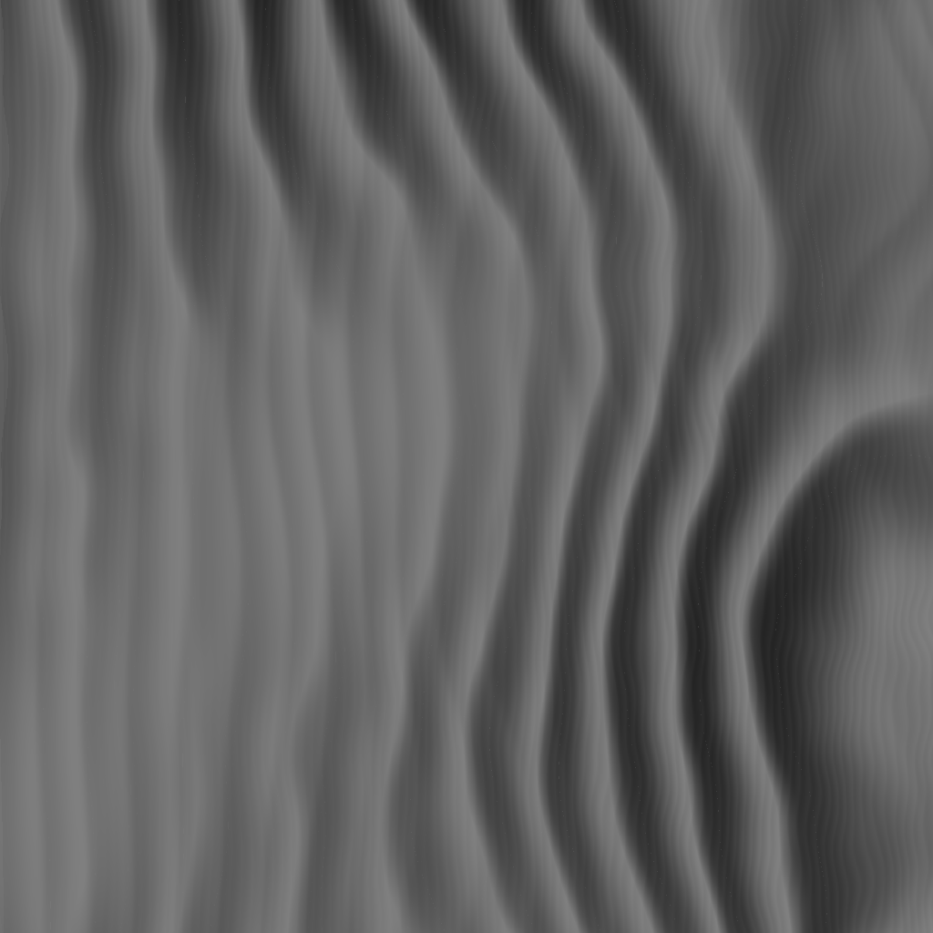
Last time I ended with a picture showing a height map of a desert scene. Since then I’ve been hard at work to convert that image into something more appealing to look at.


Not-so-sexy stuff


A lot had to happen to make that a reality. These are the nitty-gritty, not-so-sexy things that comprise a lot of game development. I’ll mention them briefly for completeness’ sake.


  • I used some of the built-in functionality of Windows to create a window to actually show something in.
  • We need to set up message handling, so our program responds correctly when the user does anything with the widow, like resizing and pressing keys and such.
  • After we have our window, we need to set up all the stuff that’s needed to draw something in 3d.


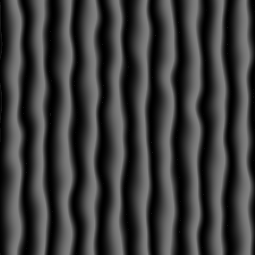
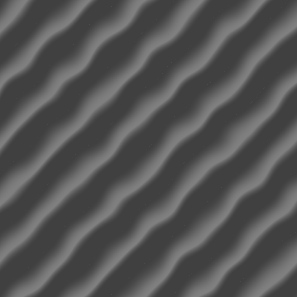
So with that out of the way, let’s get on with the good stuff! We need to convert the picture below into a three dimensional representation. Astute readers may notice this is a different picture than before. That is because when I used the previously generated height map the result wasn’t very nice. So I tweaked the settings a bit to improve the look of the scene.
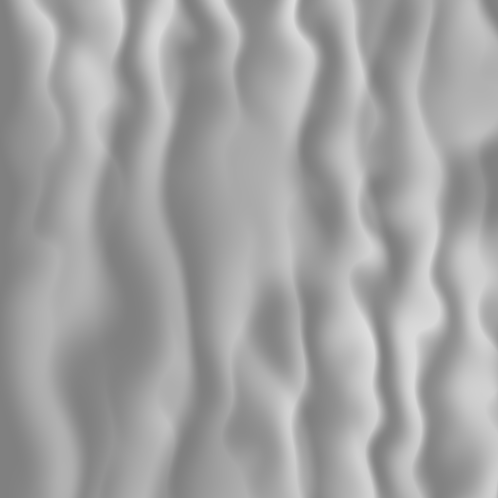


Triangles, you say?


We are going to create a triangle mesh. Basically, we are creating some space between the pixels in the above image and tie a piece of virtual string from each pixel to its neighbours in such a way that we form two triangles for every four adjacent pixels. Like in this image.


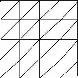
There are actually multiple ways of doing that and some schemes have certain advantages over the others. But let’s keep things simple for now. We will revisit the terrain generation multiple times and improve it each time.


Each element with a string attached to it is called a vertex. The colour of the pixel in the height map will determine the height of the vertex. Dark means low and lighter means higher. So after we’re done tying strings we end up with this screenshot.  


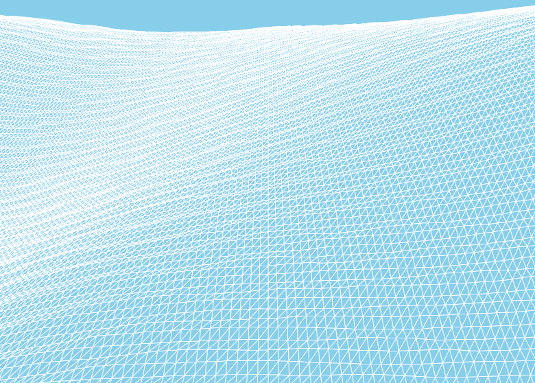
Of course, in code we don’t actually tie any strings. There are numerous ways to create triangle meshes, but all of them boil down to telling the graphics card in which order the vertices (plural of vertex) are supposed to be read. Generally, every sequence of three vertices will form a triangle.


The above image doesn’t look like a desert. To make it look like one, we need to tell the graphics card how to colour each part of the triangle. To do that we use something called a shader. I’m not going to go into details about what exactly a shader is, because that would make this post even longer than it already is and it really deserves a post of its own. Suffice it to say, in our shader we are going to tell the graphics card how the sun should light up the desert. But in order for that to work we first need something else. Something called normals.


Light our darkest hour


So what exactly is a normal? Basically if you would poke a stick in the sand and make sure it is at 90 degrees with the surface it is sticking out of, you have something representing a normal. A normal is used to indicate the orientation or direction of the vertex or triangle it is a part of.


Turns out normals are useful for a lot of things. But for now, we are going to use them to found out if our surface is facing the sun. If it is, it should be bright. If it isn’t, it should be darker.


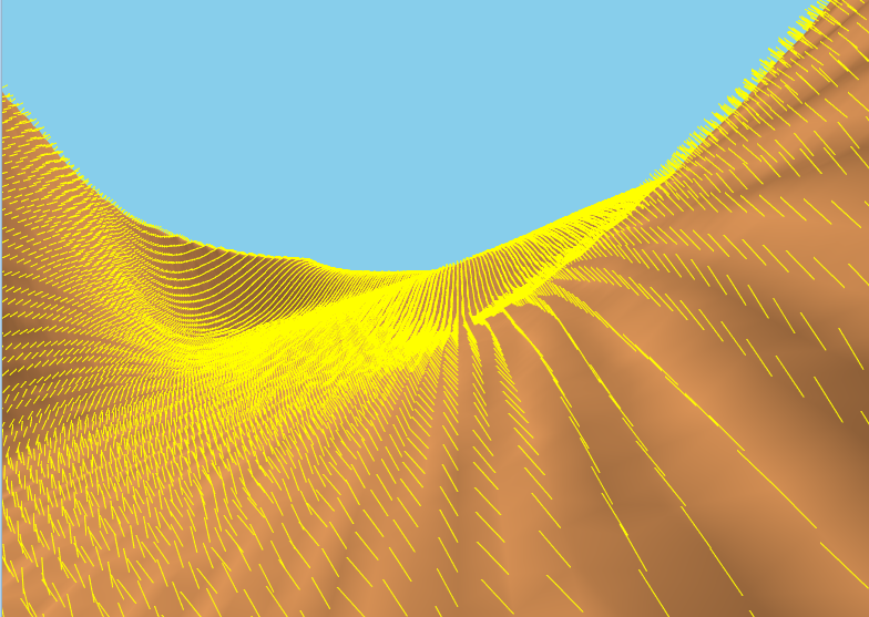
We are going to calculate our normals with something called the finite difference method. Basically it is a mathematical trick to find the slope of something. And if we know the slope, we know the normal.


Normally, normals are not drawn. They are only used for calculations. However, for educational purposes, and to check if my math is correct I’ve drawn them any way. So here they are.


After we have our normals we can proceed to write our lighting calculations. For now, we will use a lighting model called Phong lighting. It is used in a lot of games, because it is cheap to compute which means good performance. In the future, we will revisit the lighting and improve it.


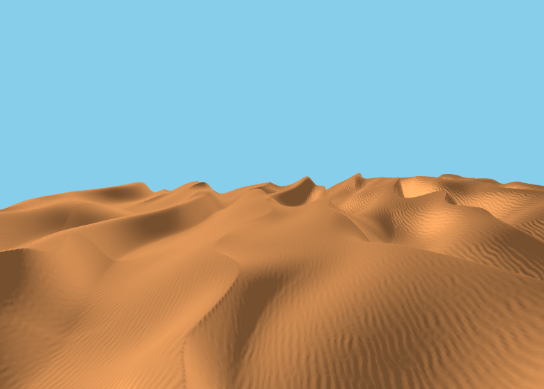
So after all that we finally have our desert scene! There is still a lot to improve, but we’re making progress. During the making of this desert scene, I found out I really need a better way to move the camera around. Right now, the view point is hard coded and that is woefully inadequate. So next we’ll be handling keyboard and mouse input. 


February 3, 2018
Floris Groen
Uncategorized

Creating a sandy desert, first try

Last blog post I mentioned a forum that contains a tutorial for Terragen (terrain generating program) to generate a desert scene. I took the math from that tutorial to try it myself. This blogpost will be about the results of my trials. Basically what I’m trying to create is something like this image.


The equation in the tutorial looks as follows. Don’t worry if you don’t understand the math. Understanding the equation is not necessary to follow along with this blog post.


There are a number of variables in this equation.


p is either zero or one and is used to select the dune profile, rounded or with a sharp peak.

s is zero for X between 0 and Xm and one for X larger than Xm.

Xm is where the peak of the dune will be. A good value for that is 0.72.

X is the input of the function and is expected to be in the range [0..1].


Here is what the output of the function looks like. As you can see, this looks a lot like a dune.


This equation creates exactly 1 dune. If we plug that into a heightfield and output that to an image we get the following picture. This represents a dune when viewed from above. Dark areas indicate low terrain and light areas high terrain. In the future we will translate this representation to 3D, but we’re not there yet.


Here’s the relevant bit of code. Feel free to skip this part, if you’re not interested in the nerdy goodness. The function called Dune implements the equation. The function called CreateHeightField does exactly what it says on the tin. If you don’t know what a height map is then take a look at the wikipedia page. The height map function takes a function pointer so I can easily plug in other things, such as fractal brownian motion. The function called Dunes is just a wrapper around Dune so I can plug it into the height map.


#define PI 3.14159265359


double Dune(const double x, const double p, const double xm)
{
    const double s = x > 0 && x < xm? 0.0f : 1.0f;

    const double ps1 = p * s + 1.0;

    const double part1 = ps1 * 0.5;
    const double part2 = 1 - cos((PI / ps1) * ((x - s) / (xm - s)));

    return (part1 * part2) - 1;
}


float Dunes(const int x, const int y, const int width, const int depth)
{
    return Dune(x / (float)width, 1, 0.72);
}


typedef float(*GetHeight)(const int x, const int y, const int width, const int depth);


void CreateHeightField(const int width, const int depth, float* const heightField, GetHeight getHeight)
{
    for (int x = 0; x < width; ++x)
    {
        for (int y = 0; y < depth; ++y)
        {
            const int index = y * width + x;
            const float z = getHeight(x, y, width, depth);
            heightField[index] = z;
        }
    }
}


int main()
{
    const int width = 1024;
    const int depth = 1024;
    float* const heightField = (float*)std::malloc(sizeof(float) * width * depth);


    CreateHeightField(width, depth, heightField, Dunes);


    std::free(heightField);
}


There are two issues we need to address. Firstly because a desert with one dune isn’t particularly interesting we need to make more dunes. And secondly this dune looks kinda straight and boring. Not very realistic at all.


To fix the first issue we’re going to introduce a couple of new things. We need a way to specify how many dunes we are creating and a way to actually make more dunes. The first we are going to achieve by adding a variable called frequency and multiply that with our input. The second by adding a modulo operator. If we create a picture based on that it looks like this:


This results in the following code.


float Dunes(const int x, const int y, const int width, const int depth)
{
float frequency = 10;
float xa = (int)(frequency * x) % width;

return Dune(xa / (float)width, 1, 0.72);
}

To fix the boring straight look of our dunes we’re going to introduce a bit of randomness. The way we do that is to use visual noise. Think of when you try to take a picture with a camera when it is dark out. The picture will often appear grainy. This grain is noise. Noise is very useful in computer graphics. Perhaps in a future blog post I will explain why noise is useful and what can be done with it (Hint, a lot).  However, not just any noise will do. It needs to have some special properties for it to be useful for us. Simplex noise will do the trick. If we output that to an image it looks like the following.


The code to achieve this effect look like this.


float Dunes(const int x, const int y, const int width, const int depth)
{
float frequency = 10;
float shift = 100.0f * SimplexNoise(5.0f * x / (float)width,
5.0f * y / (float)depth);

float xa = (int)(frequency * x + shift) % width;

return Dune(xa / (float)width, 1, 0.72);
}

This already starts to look at lot better. To have even more control over the output we introduce some more parameters. We also want to control how much distance there is between each dune. To do that we introduce a gap variable. To control the height of each dune we create an amplitude control and it would be also quite nice if we could change the wind direction as well. To do that we rotate the dunes. Here’s the output.


and here’s the code. If we want to have more randomness we can always multiply the variables with some noise. 


float Dunes(const int x, const int y, const int width, const int depth)
{
float frequency = 10;
float shift = 100.0f * SimplexNoise::noise(5.0f * x / (float)width,
5.0f * y / (float)depth);
float rotation = -PI / 4.0f;
float amplitude = 0.5f;
int gap = 400;

float xb = (x * cos(rotation) - y * sin(rotation));
int xa = (int)(frequency * xb + shift) % (width + gap);

if (xa < 0) xa = 0;
if (xa > width) xa = width;

return amplitude * Dune(xa / (float)width, 1);
}

Finally, to create an actual desert scene, we are going to combine several layers of dunes with different settings for each layer. I’m still experimenting with the best way to combine each set of dunes. For now I settled on using simplex noise as a weight for each layer and simply adding all the layers together. The final result looks like this.


There are definitely still problems with this result, such as that there are small wind ripples also on the collapsing side of the dunes, which doesn’t make sense. I’m not entirely happy with how the larger dunes combine. Some ideas that were in the original tutorial I have not expressed in code yet. For now though, this result is good enough.


Next, I will convert this into 3D geometry, so we can better see what this desert actually looks like! 

January 19, 2018
Floris Groen
Uncategorized